How Paging Works?
When the OS executes a program (via exec system call), the first job is to set up necessary control structures without loading the actual code or data yet.
Reserve Resources
The OS kernel must identify and reserve a pool of free physical memory frames that the new program might need. (so that the OS does not have to search the free frame list every time the Page Fault occurs.)
Setup the Page Table
The OS creates the new program's Page Table in a reserved area of the physical memory.
For every logical page the program defines (Text, Data, Stack etc.), the OS creates a 2-word Page Table Entry (PTE).
OS sets special marker -1 and valid bit to 0, write bit is set accordingly
Context Initialisation
The OS loads the Page Table's starting address into the PTBR
The OS loads the Page Table length into PTLR
The instruction point (IP) is set to the program's starting address (found in the header)
At this point, the program is loaded, but no actual code or data is in the RAM.
On-Demand Loading
Processes the logical address, and finds the valid bit to be 0 -> Page Fault Exception
Control is transferred to the OS kernel's Exception Page Number register to which logical page is needed, finds a free frame and the loads the data
Update the Page Table
It writes the number of newly used Frame into this word, it sets the valid bit to 1.
Page Table
Every user mode program has an associated page table which maps its virtual address space to machine's physical address space. For the hardware address translation to work, the address of the page table must be stored in PTBR and the number of entries in this Page Table must be stored in the PTLR. The page table must be set up in Privileged Mode.
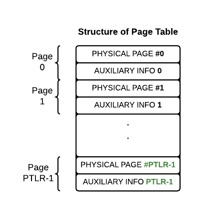
The page size for the XSM Architecture is 512 words. Each Page Table Entry is 2 words long
Word 1: Physical Page Number
This word stores the physical page number in the main memory where the corresponding logical page of the user program is currently loaded.
-
Valid Entry: If this word holds a valid PPN (a number greater than or equal to 0), the entry is considered valid.
-
Invalid Entry: If the page has not been loaded into memory (e.g., it is swapped out to disk), the entry is considered invalid (often represented by a negative number like -1).
Word 2: Auxiliary Flag Bits
| Bit | Name | Function | Set By | Initial State | Exception |
|---|---|---|---|---|---|
| R | Reference Bit | Tracks if the page has been accessed in user mode since it was last made valid (used by OS replacement algorithms). | Hardware (set to 1 on first access). | 0 (unreferenced) by the OS. | N/A |
| V | Valid/Invalid Bit | 1 if the page is loaded in physical memory (Word 1 contains a valid PPN); 0 otherwise. | OS | Set by the OS. | If access is attempted when V=0, the machine triggers a Page Fault Exception. |
| W | Write Permission | 1 if the user program can write to the page; 0 (Read-Only) otherwise. | OS | Set by the OS. | If the program attempts to write when W=0, the machine triggers an Exception Handler routine. |
| D | Dirty Bit | Tracks if the page's content has been modified by any instruction while in user mode. | Hardware (set to 1 upon any write/modification). | 0 (clean) by the OS. | N/A |
The Address Translation Scheme
Logical Page Number = Logical Address / 512
Location of Page Table Entry = PTBR + 2 x Logical Page Number
Physical Page Number = Value stored at [Location of Page Table Entry]
Offset (Position within the page itself) = Logical Address mod 512
Physical Address = (Physical Page Number x 512) + Offset
-
EIP (Exception Instruction Pointer): Contains the Virtual IP address (e.g.,
40). -
EPN (Exception Page Number): Contains the Logical Page Number that caused the fault (e.g.,
02). -
EC (Exception Cause): Contains the cause code (e.g.,
0for a page fault). -
EMA (Exception Memory Address): Contains the full Logical Address that triggered the fault (e.g.,
1032).