Introduction
Module
Physical Layer
- Analog and Digital Transmission - Signal and composite signals, time and frequency domain Digital signal transmission (baseband and broadband transmission) Transmission impediments (attenuation and noise)
- Digital Signals
-
Analog Signals
-
Peak Amplitude
- Period and Frequency
Two types of graphs - Time-domain plot - Frequency-domain plot
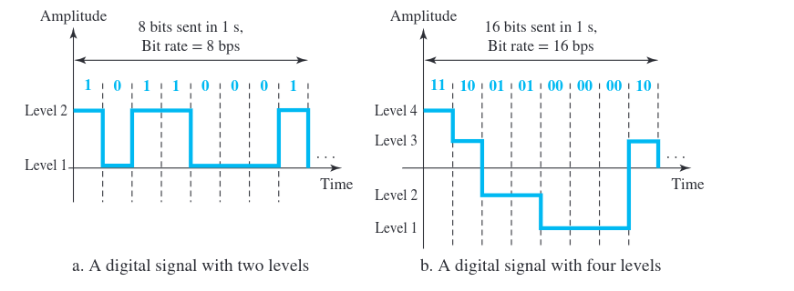
Digital Signals
Bit Rate
- Bit rate is the number of bits sent in 1s , expressed in bits per second.
Example 2.3
100 pages per minute, 10/6 pages per second
A page is an average of 24 lines with 80 characters in each line, each character requires 8 bits

24 * 80 * 8 * 100 / 60 -> 1.536/60 Mbps
Bit Length
The distance occupied by 1 bit $Bit length$ = $1 / (bit rate)$
Transmission of Digital Signals
1) Baseband - No conversion to analog signals 2) Broadband - Converts to analog signals
Signal Impairment
1) Attenuation - Loss of energy, requires amplification $10\log_{10}{(P2/P1)}$
2) Distortion - Signal changes its form or shape. 3) Noise - Thermal Noise - Random motion of electrons - Induced Noise - External Sources - Crosstalk - Effect of one wire on other - Impulse Noise - spike in signal
Signal-to-Noise- Ratio (SNR)
$SNR = (Average signal power) / (Average noise power)$
- Described in decibels $SNRdb = 10\log{10}{SNR}$
Data Rate Limits
- Bandwidth available
- Level of the signals we use
- The quality of the channel (level of noise)
Nyquist Bit Rate
BitRate = $2 * B * \log{2}{L}$
Example
We need to send 265 kbps over a noiseless (ideal) channel with a bandwidth of 20 kHz. How many signal levels do we need? We can use the Nyquist formula as shown: $265000 = 2 * 20,000 * log{2}{L} \implies 98.7 levels$ Sound Level should be in powers of 2, so either accept $L = 64 (265 kbps)$ or $L = 128 (280 kbps)$
Shannon Capacity (Noisy Channel)
Channels are always noisy.
$C = B * log{2}{(1 + SNR})$
Topic
SNR, Data rate limits (Nyquist bit rate for
noiseless channel and Shannon Capacity for noisy channel) Digital-to-digital transmission (line coding – NRZ, NRZ-L and NRZ-I, RZ, Manchester Analog signal to digital data:
Digital Transmission
Digital-to-Digital Conversion
- Line coding is the process of converting digital data to digital signals
Line Coding
NRZ

- Cons - baseline wander (average of the signal to distinguish high and low signals)
- Non-return to zero inverted
NRZI
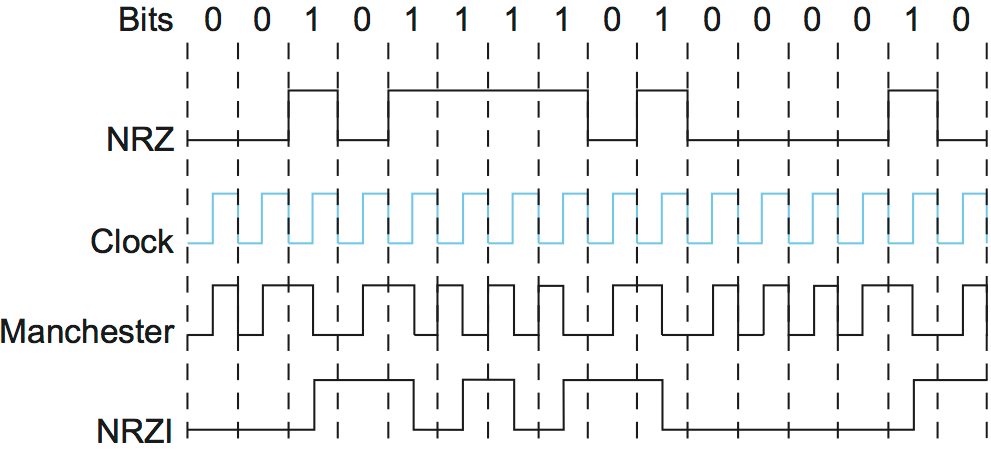
Manchester Encoding and Differential Manchester
- Dr Thomas and IEEE standards <- (Often used)
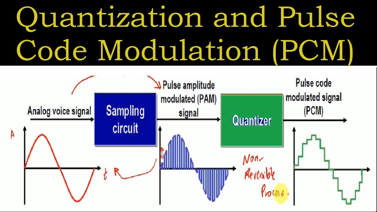
Analog-to-Digital Conversion
- Pulse Code Modulation (PCM)
- Sampling, Encoding and Quantizing
- Sampling is the process of measuring the amplitude at regular intervals
- $f_s>=2*f_{max}$
- $BitRate = f_s * n * c$
- $c \implies number of channels$
- $n \implies number of bits per sample$
- $B_{min} = n_b * B_{analog}$ Sampling generates pulses whose amplitudes match the sampled signal. These pulses are sent in a sequence for transmission.
$Quantization$ - Converting each sampled amplitude into a finite set of discrete levels. $$ Δ = (Vmax − Vmin)/L, L = 2^n$$