Virtual Lan
1. The Concept and Evolution
To understand VLANs, you must understand the problem they solve regarding Physical vs. Logical Topology.
-
The Old Way (Geography trumps Organization): In early Ethernet setups, cables snaked through buildings. Every computer plugged into a specific cable was on the same LAN. If you sat next to someone from a different department, you were physically wired to the same network, regardless of whether you needed to share data with them.
-
The Evolution (Centralized Wiring): In the 1990s, companies moved to centralized wiring closets using hubs and switches. Every office had a wire running to a central room.
-
The VLAN Solution (Rewiring via Software): VLANs allow network administrators to decouple the logical topology from the physical topology. Instead of unplugging and moving cables to move a user to a different network, administrators can configure the switch via software to assign a specific port to a specific LAN.
Based on the provided text (specifically Section 4.8.5), here is a detailed explanation of Virtual LANs (VLANs) tailored for your final exam preparation.
2. Why use VLANs? (The Motivations)
The text highlights four specific reasons why an organization would implement VLANs:
-
Security:
-
Different departments have different security needs. For example, "Human Resources" servers containing salaries should not be accessible by the "Public Web Server."
-
VLANs isolate these groups completely. Management cannot be accessed from the guest network, even if they are on the same physical switch.
-
-
Load Management:
-
Some departments (e.g., Research) might run heavy experiments that saturate the network bandwidth.
-
VLANs separate this heavy traffic so it does not degrade the performance of other departments (e.g., Management videoconferencing).
-
-
Broadcast Traffic Control (Broadcast Storms):
-
Many protocols rely on broadcasting (sending a frame to everyone on the LAN). As the number of computers grows, the frequency of broadcasts increases, consuming capacity.
-
Broadcast Storms: Sometimes a network interface card breaks and generates an endless stream of broadcasts. This can cripple every computer on the network as they try to process the garbage frames.
-
VLANs limit the "blast radius" of a broadcast. A broadcast sent on VLAN 1 is not forwarded to VLAN 2.
-
-
Organizational Flexibility:
-
Physical wiring often doesn't match how teams work (e.g., cross-functional teams located in different offices).
-
Employees move offices frequently. VLANs allow an administrator to change a user's LAN assignment without changing their physical location or recabling.
-
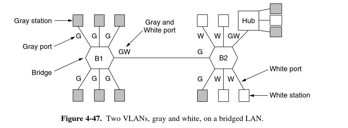
How to transmit the packets based on the vlans?
IEEE 802.1Q
Because there can be computers (and switches) that are not VLAN aware, the first VLAN-aware bridge to touch a frame adds VLAN fields and the last one down the road removes them. An example of a mixed topology is shown in Fig. 4-48. In this figure, VLAN-aware computers generate tagged (i.e., 802.1Q) frames directly, and further switching uses these tags. The shaded symbols are VLAN-aware and the empty ones are not.
4. The Standard: IEEE 802.1Q
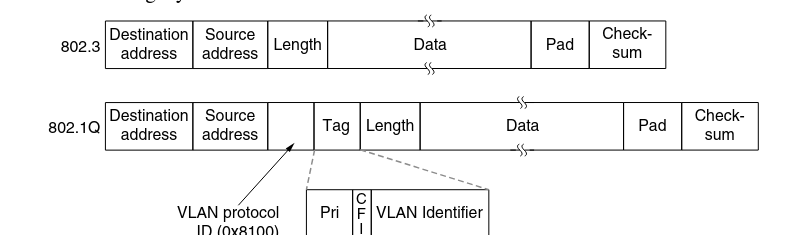
To implement VLANs, the networking industry had to change the Ethernet header. This standard is known as IEEE 802.1Q.
The Challenge: How do you tell which VLAN a frame belongs to? The Solution: Tagging.
The 802.1Q Frame Format
The standard inserts a VLAN Tag into the Ethernet header. This tag consists of two 2-byte fields (total 4 bytes added):
-
VLAN Protocol ID (0x8100):
-
This 2-byte field is inserted where the Length/Type field usually sits.
-
The value
0x8100is greater than 1500, so legacy Ethernet cards interpret it as a "Type" rather than a "Length." This signals that the frame is 802.1Q tagged.
-
-
Tag Control Information (2 bytes):
-
VLAN Identifier (12 bits): This is the "color." It identifies which VLAN the frame belongs to (allowing up to 4,096 unique VLANs).
-
Priority (3 bits): Allows distinction between hard real-time traffic (like Voice over IP) and soft real-time or data traffic. This enables Quality of Service (QoS).
-
CFI (1 bit): Canonical Format Indicator. Originally for compatibility with Token Ring addresses (mostly irrelevant now).
-
Note: Because 4 bytes are added, the maximum frame size was raised from 1518 bytes to 1522 bytes.
Summary Checklist for Exam
-
Definition: Decoupling logical topology from physical topology.
-
4 Reasons to use: Security, Load, Broadcast control, Flexibility.
-
Standard: IEEE 802.1Q.
-
Header Change: Adds a 4-byte tag including a 12-bit VLAN ID and 3-bit Priority field.
-
Operation: Switches add tags on ingress and remove them on egress for legacy devices.